![]()
![]()
![]()
![]() DB-UML Modeling Tool
DB-UML Modeling Tool
Guide
© 2007 Cincom Systems, Inc.
All Rights Reserved
![]()
![]()
![]()
![]() DB-UML Modeling Tool
DB-UML Modeling Tool
Guide
© 2007 Cincom Systems, Inc.
All Rights Reserved
DB-UML is an open source modeling tool for creating, updating and visualizing relational database schemas. A UML profile is used to represent database elements (see the UML Database Modeling paper). Using the tool you can create a new model of database elements, import relational catalog meta-data into a model and generate SQL create statements from a model.
The tool is designed as an ArgoUML module. ArgoUML is the leading open UML modeling tool. For information on ArgoUML see http://ArgoUML.tigris.org/ DB-UML extends ArgoUML allowing you to create two new kinds of diagrams – database deployment diagrams and schema diagrams.
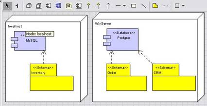
Database deployment diagrams show the relationships between physical nodes and databases. They can also show the schemas defined in a database.
Database schema diagrams are similar to class diagrams. They show the structure and relationships of schemas, tables, views and other database entities.
You can download and install DB-UML with an existing ArgoUML installation or you can download and install DB-UML bundled with ArgoUML.
After downloading and expanding the DB-UML archive file, the following jars must be moved to ArgoUML’s ext folder:
dbuml.jar
commons-collections-3.0.jar
velocity-1.4.jar
When you run ArgoUML, it will then install DB-UML as a module. Be sure the DB-UML archive version number is compatible with your ArgoUML version.
You must also define any JDBC drivers needed to connect to databases for importing catalog information. For example, the following command defines the CLASSPATH for ArgoUML, the PostgreSQL JDBC driver and the DB-UML module and starts ArgoUML:
java –cp argouml.jar;c:\dbuml\lib\postgresql-8.2-505.jdbc2.jar;ext\dbuml.jar org.argouml.application.Main
Download and expand the DB-UML archive file that is bundled with ArgoUML. You must define any JDBC drivers needed to connect to databases for importing catalog information. For example, the following command defines the CLASSPATH for ArgoUML, the PostgreSQL JDBC driver and the DB-UML module and starts ArgoUML:
java –cp argouml.jar;c:\dbuml\lib\postgresql-8.2-505.jdbc2.jar;ext\dbuml.jar org.argouml.application.Main
After staring ArgoUML you can view a sample project by opening sample.zargo distributed in the tests/projects file. The project contains elements from a PostgreSQL database and MicroSoft Access database. By selecting the Database Deployment Diagram you can view the database elements and the schemas they contain.
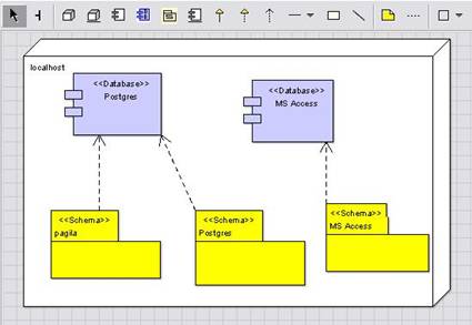
In DB-UML, database elements must be contained in a schema (in UML terminology, they must have a schema namespace). If an element does not belong to a schema, the convention is to have element contained in a “default” schema having the same name as the database. Also, if the database does not support schemas, the convention is to have the element contained in a “default” schema having the same name as the database.
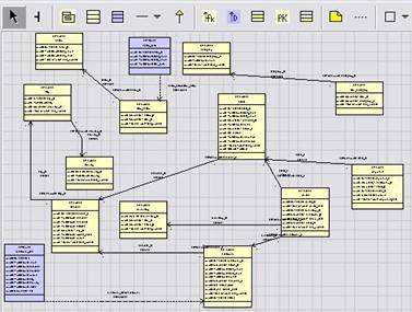
You can view the elements in the Pagila schema by selecting the Paliga Schema Diagram.
This shows the tables, views and foreign key relationships in the schema.
By right clicking on elements in a diagram you can see the additional actions that are available. For example, right clicking on the Postgres database in the Database Deployment Diagram:
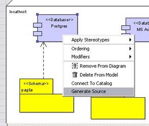
You will find the Connect to Catalog and the Generate Source actions. To connect you need to have a PostgreSQL database available and you must load the Pagila database elements. If you would like to do this, see the instructions in the Sample Schemas section.
If you select the Generate Source action you will be asked to name a file to store the SQL statements. Also a dialog will be shown for the generated source. When you generate source, SQL statements will be generated for the element selected and all the elements it contains. So if you generate source for a database, SQL statements will be generated for the database, the schemas it contains, the tables contained by the schemas, etc. Also, the SQL statements will be created in the correct order. For example, a SQL create statement for a schema will be generated before the create statement for a table contained by the schema.
DB-UML only displays actions if they are available for use. For, example, if you are not connected to a database catalog, then you will not see the “Import from Catalog” or “Update Catalog” actions. Also, actions will only be shown for database elements if they part of a well-formed model. A model is well-formed if:
1. Schemas are related to a Database through a dependency.
2. Other database elements are contained in a Schema (in the Schema namespace).
We will now show how you can import databases elements from a catalog to your project, add more elements to the project and update the database catalog. We will be using PostgreSQL and the Pagila database but you can follow the steps using another database. Be sure your CLASSPATH has the jar file for the JDBC driver you need.
In your new project:
1. Select Tools > New Database Deployment Diagram.
2. Add a Node figure to the diagram and name the Node “localhost”.
3. Add a Database figure to the diagram inside the localhost Node and name it “Postgres”.
Your diagram should now look like:
It is not necessary to use Nodes in your deployment diagrams but they serve to document your physical database configuration.
Now select the Database figure and choose the “Tagged Values” tab. DB-UML uses tagged values to store the properties of elements.
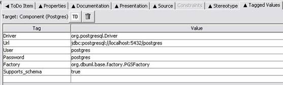
For Database elements the properties describe how to connect to the database and database specific implementation classes. To connect to the database you must supply a Driver class name, a connection URL, a User name and a Password. You also need to specify if the database supports schemas.
As databases may implement non-standard features and may not strictly follow SQL standards you can also specify database specific implementation classes. These classes are created by a factory class. The current choices are:
1. PostgresSQL – org.dbuml.base.factory.PGSFactory;
2. MySQL - org.dbuml.base.factory.MySQLFactory;
3. Oracle - org.dbuml.base.factory.OraFactory;
4. Generic - org.dbuml.base.factory.GenericFactory;
If a database specific factory is not available you can use the generic factory.
Now select the Database figure and choose “Connect to Catalog”. If connection is successful the Database figure outline will change colors.
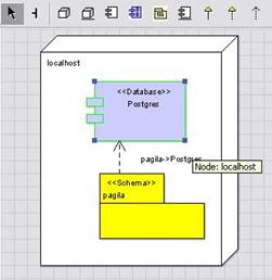
Next select “Import from Catalog > Import Schemas” and choose a Schema to import. If you loaded the Pagila sample database you can choose the “pagila” schema. The Schema will appear in the explorer beneath the Database and you can drag it to the diagram. Your diagram should now look like:
If your database catalog does not have schemas defined or does not support schemas you can add a default schema to your project:
1. Select the Schema figure in the toolbar and add the figure to the diagram;
2. Give the Schema the same name as the Database. This defines it as the “default” schema.
3. Add a dependency between the Schema and the Database.
You can now select the Schema figure and import tables or views to the model. For the Pagila Schema we can import the “actor” table. After the import the table will appear in the explorer beneath the Schema.
We are now ready to work on modifications to the Pagila Schema so we create a “Database Schema Diagram” from the tools menu. You can then drag the Schema and Table to the diagram. Your Database Schema diagram should now look like:
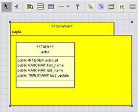
In our project, the “actor” Table is contained in the “pagila” Schema. This relationship was established when the Table was imported. In the diagram it is not necessary to have the Schema figure contain the Table figure but this helps to document the relationship.
Let’s say we want to add an “agency” Table to our database so that we know the agency representing the actors. We select a Table with the toolbar and add the Table to the diagram and name the Table “agency”. If we place the “agency” Table inside the Schema figure, the Table will be contained in the Schema. Another way to do this is:
1. Select the “agency” Table and choose the Properties tab.
2. Select the “pagila” Schema as the Namespace.
To establish a relationship between actors and agencies we draw a Foreign Key relationship between the “actor” and “agency” Tables. So far, the diagram looks like the following:
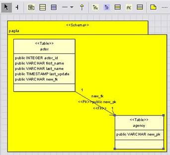
When we added the Foreign Key relationship a Foreign Key Column was added to the “actor” table and a Primary Key Column was added to the “agency” table. We can re-name the Foreign Key Column to “agency” and the Primary Key Column to “agency-name”. We can also rename the relationship to “my-agency”.
To complete the “agency” table we will add an address column. Right click on the “agency” Table and select “Add > New Column”. We can rename this to “address” and select LONGVARCHAR as the type. Note that if your database supports additional types you can import the types. From the Database, select “Import from Catalog > Import Attribute Types”.
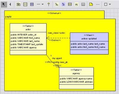
To show an example of a View, we can construct a View that shows actors with information updated this year:
1. Add a View to the diagram from the toolbar and rename the view to “actors-updated”.
2. Draw a Derived relationship between the View and the “actor” table.
3. Right click on the View and select “Add > Column(s) from base(s)”.
4. Choose the name columns to add to the View.
The diagram should now look like:
The select statement for a View is stored in the tagged value SQL_QUERY. To select actors changed this year we use:
SELECT
last_name, first_name FROM actor WHERE
EXTRACT(YEAR
FROM last_update) = EXTRACT(YEAR FROM CURRENT_TIMESTAMP)
Now we have completed our changes to the pagila schema and we would like to update the database catalog. You can review the SQL statements used to create elements by selecting the source tab and choosing the SQL language. For example, the SQL statements needed to create the View we added are:
/*
Create View pagila.actor_updated */
CREATE
VIEW pagila.actor_updated
(last_name
, first_name )
as
SELECT
last_name, first_name FROM actor WHERE EXTRACT(YEAR FROM last_update) =
EXTRACT(YEAR FROM CURRENT_TIMESTAMP)
You can also generate a file of SQL statements used to create elements by right clicking the element and choosing Generate Source. This generates statements to replace the elements in the database catalog. SQL DROP statements are generated followed by SQL CREATE statements.
You can also execute the generated statements by selecting the Update Catalog action.
Several sample database schemas are provided that are used by the sample.zargo project. The schemas can be found in the tests\databases folder.
The Pagila schema demonstrates many of the features of PostgesSQL. You can load the schema using:
psql -f pagila-schema.sql -h localhost -p 5432 postgres "postgres"
This uses a database named “postgres” on port 5432 with the user “postgres”.
When you open the sample.zargo project, you can connect to the database using the “Postgres” Database element. If you use a different database name, port number or user name, you can change the tagged values of the Database element to match.
The NorthWind database is often used to demonstrate Microsoft tools. The sample.zargo project uses this database with Microsoft Access. To set up the database:
1. In Windows choose Control Panel > Administrative Tools > Data Sources (ODBC)
2. Create a new data source choosing the MicroSoft Access Driver.
3. Name the data source “MS Access Database” and select the sample database tests\databases\NorthWind\northwind.mdb.
When you open the sample.zargo project, you can connect to the database using the “MS Access” Database element. This uses the Sun JDBC-ODBC driver to bridge JDBC requests issued by DB-UML to the Access ODBC driver.